单周期 CPU 设计 
约 1334 个字 248 行代码 5 张图片 预计阅读时间 8 分钟
Abstract
计算机系统 Ⅰ lab5-2 实验报告(2022.05.27 ~ 2022.06.21)
Warning
仅供学习参考,请勿抄袭
实验内容 
- 完成控制单元模块设计
- 结合数据通路,搭起单周期 CPU
- 使用 lab5-1 的仿真代码文件进行仿真测试
- 使用 lab5-1 的测试环境进行上板验证
- bonus:指令扩展
- 实现 andi ori and or sll
- 实现 xori slli srli srl
- 实现 auipc sltu jalr
控制单元模块设计 
直接以 bonus 为目标进行设计,完成这 22 个指令:lw sw bne beq jal lui addi add slt slti andi ori and or sll xori slli srli srl auipc sltu jalr
明确目标 
目标即编写 lab5-1 中给出的 Control.v 中的 Control 模块的编写,其功能就是接收指令并译码,解析出一系列数据通路中会用到的值。其输入输出部分:
module Control (
    input   [6:0]   op_code,
    input   [2:0]   funct3,
    input           funct7_5,
    output  [1:0]   pc_src,
    output          reg_write,
    output          alu_src_b,
    output  [3:0]   alu_op,
    output  [1:0]   mem_to_reg,
    output          mem_write,
    output          branch,
    output          b_type,
    output          auipc;
);
输出为译码得到的一些结果:
- pc_src:pc 来源,00 来自 pc+4、01 来自 JALR、10 来自 JAL
- reg_write:是否写入寄存器组
- alu_src_b:ALUsrc,0 表示 ALU 的第二个操作数来自寄存器,1 表示来自立即数
- alu_op:ALU 进行的操作符,在 AluOp.vh 中定义
- mem_to_reg:写回寄存器的数据来源,00 写回数据来自 ALU、01 来自立即数、10 来自 pc+4、11 来自 data memory
- mem_write:是否写入 data memory,0 表示读,1 表示写
- branch:指令是否是 branch 分支操作,1 表示是,0 不是
- b_type:分支操作类型,0 表示 bne、1 表示 beq
此外,我增加了一个 auipc 的输出来显示当前指令是否为 auipc,使 Datapath 中做特殊处理。
剩余部分几乎与 lab5-1 一致,只需要替换 Control.v 文件并做一些相应的适配性更改即可。
指令分析 
将所需要实现的 22 个指令根据 opcodes 分类:( 下表中 ps 代表 pc_src,rw 代表 reg_write,as 代表 alu_src_b,op 代表 alu_op,mtr 代表 mem_to_reg,mw 代表 mem_write,b 代表 branch,bt 代表 b_type,空格表示不需要考虑,- 表示在下面写 )
| opcode | 指令 | ps | rw | as | op | mtr | mw | b | bt | auipc |
|---|---|---|---|---|---|---|---|---|---|---|
| 0000011 | lw | 0 | 1 | 1 | ADD | 11 | 0 | 0 | 0 | |
| 0100011 | sw | 0 | 0 | 1 | ADD | 0 | 1 | 0 | 0 | |
| 0010011 | addi slti xori ori andi slli srli |
0 | 1 | 1 | - | 0 | 0 | 0 | 0 | |
| 1100011 | bne beq | 0 | 0 | 0 | XOR | 0 | 0 | 1 | - | 0 |
| 1101111 | jal | 10 | 1 | 10 | 0 | 0 | 0 | |||
| 0110111 | lui | 0 | 1 | 10 | 0 | 0 | 0 | |||
| 0110011 | add slt and or sll srl sltu |
0 | 1 | 0 | - | 0 | 0 | 0 | 0 | |
| 0010111 | auipc | 0 | 1 | 1 | ADD | 0 | 0 | 0 | 1 | |
| 1100111 | jalr | 1 | 1 | 1 | ADD | 10 | 0 | 0 | 0 |
对于 0010011 的一系列 I 型指令,需要通过判断 funct3 来确定 alu_op。对于 0110011 的一系列 R 型指令,可以直接使用 {funct7_5, funct3} 作为 alu_op。对于 bne 和 beq,其 b_type 就是 ~funct3[0]。
控制单元模块代码 
通过前面的分析,可以直接写出控制单元的代码:
`timescale 1ns / 1ps

module Control (
    input       [6:0]   op_code,
    input       [2:0]   funct3,
    input               funct7_5,
    output reg  [1:0]   pc_src,     // 00 pc+4 01 JALR 10 JAL
    output reg          reg_write,  // 1 写入寄存器
    output reg          alu_src_b,  // 0 来自寄存器 1 来自立即数
    output reg  [3:0]   alu_op,     // ALUop
    output reg  [1:0]   mem_to_reg, // 00 写回数据来自 ALU 01 来自立即数 10 来自 pc+4 11 来自 data memory
    output reg          mem_write,  // 0 读 memory,1 写
    output reg          branch,     // 1 是 branch 0 不是
    output reg          b_type,     // 1 是 beq 0 是 bne
    output reg          auipc       // 1 是 auipc 指令
);
    `include "AluOp.vh"
    always @(*) begin
        pc_src      = 0;
        reg_write   = 0;
        alu_src_b   = 0;
        alu_op      = {funct7_5, funct3};
        mem_to_reg  = 0;
        mem_write   = 0;
        branch      = 0;
        b_type      = 0;
        auipc       = 0;

        case (op_code)
            7'b0000011: begin   // lw
                reg_write = 1;  alu_src_b = 1;  alu_op = ADD;
                mem_to_reg = 2'b11;
            end
            7'b0100011: begin   // sw
                alu_src_b = 1;  alu_op = ADD;   mem_write = 1;
            end
            7'b0010011: begin   // addi slti xori ori andi slli srli
                reg_write = 1;  alu_src_b = 1;
                case (funct3)
                    3'b000: alu_op = ADD;
                    3'b010: alu_op = SLT;
                    3'b100: alu_op = XOR;
                    3'b110: alu_op = OR;
                    3'b111: alu_op = AND;
                    3'b001: alu_op = SLL;
                    3'b101: begin
                        if (funct7_5)   alu_op = SRA;
                        else            alu_op = SRL;
                    end
                endcase
            end
            7'b1100011: begin   // bne beq
                alu_op = XOR;   branch = 1; b_type = ~funct3[0];
            end
            7'b1101111: begin   // jal
                pc_src = 2'b10; reg_write = 1;  mem_to_reg = 2'b10;
            end
            7'b0110111: begin   // lui
                reg_write = 1;  mem_to_reg = 2'b01;
            end
            7'b0110011: begin   // add slt and or sll srl sltu
                reg_write = 1;
            end
            7'b0010111: begin   // auipc
                reg_write = 1;  alu_src_b = 1;  alu_op = ADD;
                auipc = 1;
            end
            7'b1100111: begin   // jalr
                pc_src = 2'b01; reg_write = 1; mem_to_reg = 2'b10;
                alu_src_b = 1; alu_op = ADD;
            end
        endcase
    end

endmodule
其它文件中的修改 
ImmGen 模块在上一次 lab 中就实现了对于这 22 个指令的识别,不需要更改。SCPU 模块中只需要添加一个 wire auipc 然后连接 Control 和 Datapath 的 auipc 接口即可。Core 模块及更高层的无需更改。
因为 sll slli srl srli 这些移位的指令移的位数都是取低 5 位,所以需要改一下 ALU 的代码,使其进行 SLL 和 SRL(包括 SRA)时取 b[4:0] 进行运算,即:
Datapath 需要进行一些更改:
- 对于 ALU 的第一个参数也进行一下选择,如果 auipc 为 0 则原样选择 read_data_1,为 1 则选择 pc 作为第一个参数
- PC 的选择器输入对 jal 和 jalr 进行区分,jalr 对应的地址(即四路选择器的第二路)为 ALU 的结果,jal 和 branch 对应的地址(三四路)仍为 pc+imm
更改后的 Datapath 模块:
`timescale 1ns / 1ps

module Datapath(
    input           clk,
    input           rst,
    input   [1:0]   pc_src,
    input           reg_write,
    input           alu_src_b,
    input           branch,
    input           b_type,
    input           auipc,
    input   [3:0]   alu_op,
    input   [1:0]   mem_to_reg,
    input   [31:0]  inst_in,
    input   [31:0]  data_in,
    output  [31:0]  addr_out,
    output  [31:0]  data_out,
    output  [31:0]  pc_out,
    input   [4:0]   debug_reg_addr,
    output  [31:0]  debug_reg
);
    reg     [31:0]  pc;
    wire    [31:0]  pc_next;
    wire    [31:0]  write_data, read_data_1, read_data_2;
    wire    [31:0]  alu_data_1, alu_data_2, alu_result;
    wire            alu_zero;
    wire    [31:0]  imm;
    wire    [31:0]  jal_addr, jalr_addr;

    assign pc_out = pc;
    assign addr_out = alu_result;
    assign data_out = read_data_2;

    always @(posedge clk or posedge rst) begin
        if (rst) begin
            pc <= 32'b0;
        end
        else begin
            pc <= pc_next;
        end
    end

    Regs regs (
        .clk(clk),
        .rst(rst),
        .we(reg_write),
        .read_addr_1(inst_in[19:15]),
        .read_addr_2(inst_in[24:20]),
        .write_addr(inst_in[11:7]),
        .write_data(write_data),
        .read_data_1(read_data_1),
        .read_data_2(read_data_2),
        .debug_reg_addr(debug_reg_addr),
        .debug_reg(debug_reg)
    );

    ImmGen immgen (
        .inst(inst_in),
        .imm(imm)
    );

    Mux2x32 mux2x32_1 (
        .I0(read_data_1),
        .I1(pc),
        .s(auipc),
        .o(alu_data_1)
    );

    Mux2x32 mux2x32_2 (
        .I0(read_data_2),
        .I1(imm),
        .s(alu_src_b),
        .o(alu_data_2)
    );

    ALU alu (
        .a(alu_data_1),
        .b(alu_data_2),
        .alu_op(alu_op),
        .res(alu_result),
        .zero(alu_zero)
    );

    Mux4x32 mux4x32 (
        .I0(alu_result),
        .I1(imm),
        .I2(pc + 4),
        .I3(data_in),
        .s(mem_to_reg),
        .o(write_data)
    );

    assign jal_addr = pc + imm;
    assign jalr_addr = alu_result;

    MuxPC mux_pc (
        .I0(pc + 4),
        .I1(jalr_addr),
        .I2(jal_addr),
        .I3(jal_addr),
        .s(pc_src),
        .branch(branch),
        .b_type(b_type),
        .alu_res(alu_result),
        .o(pc_next)
    );
endmodule
这样修改后整个单周期 CPU 就完整正确连接了
仿真测试 
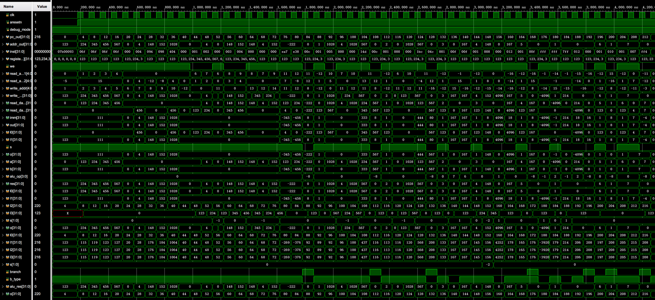
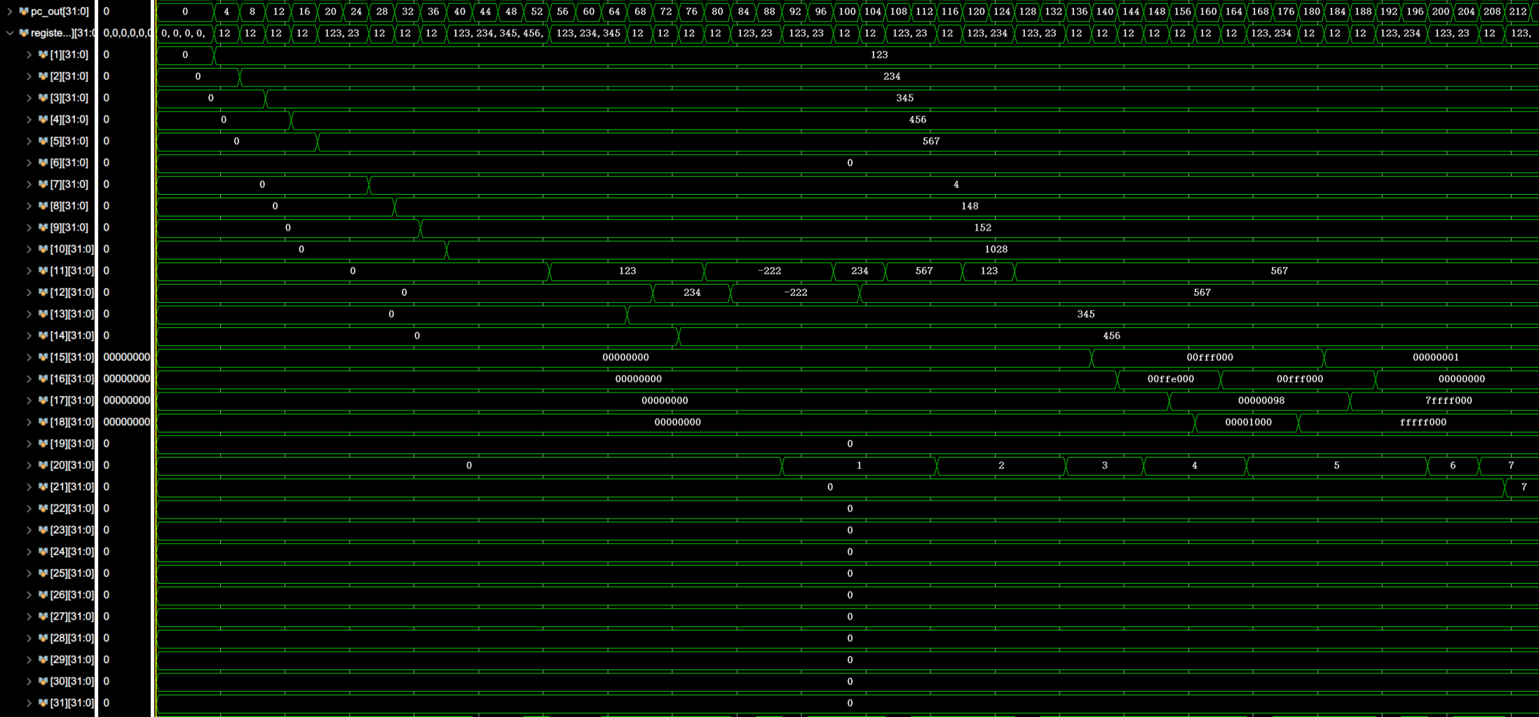
与 lab5-1 同理,载入 lab10_all.coe 文件,选择 Core_tb.sv 为目标进行仿真测试,再通过调整得到全部中间变量(寄存器组值、ALU 输入输出、Mux 输入输出等)得到仿真波形:

通过仔细分析每一条汇编指令与所有值的变化、寄存器的变化可以看出 CPU 按照给出的指令正确运行了。行为均与 lab5-1 一致。
上板验证 
在 vivado 中 disable 掉 Control_sim.v 文件(即使用 Control.v 和 Control.edf)然后通过 Top.sv 中顶层模块生成比特流,写入 FPGA 开发版即可进行上板验证。
通过单步运行,观察 pc、inst、寄存器值可以确定上板也没有任何问题。行为均与 lab5-1 一致。
Bonus
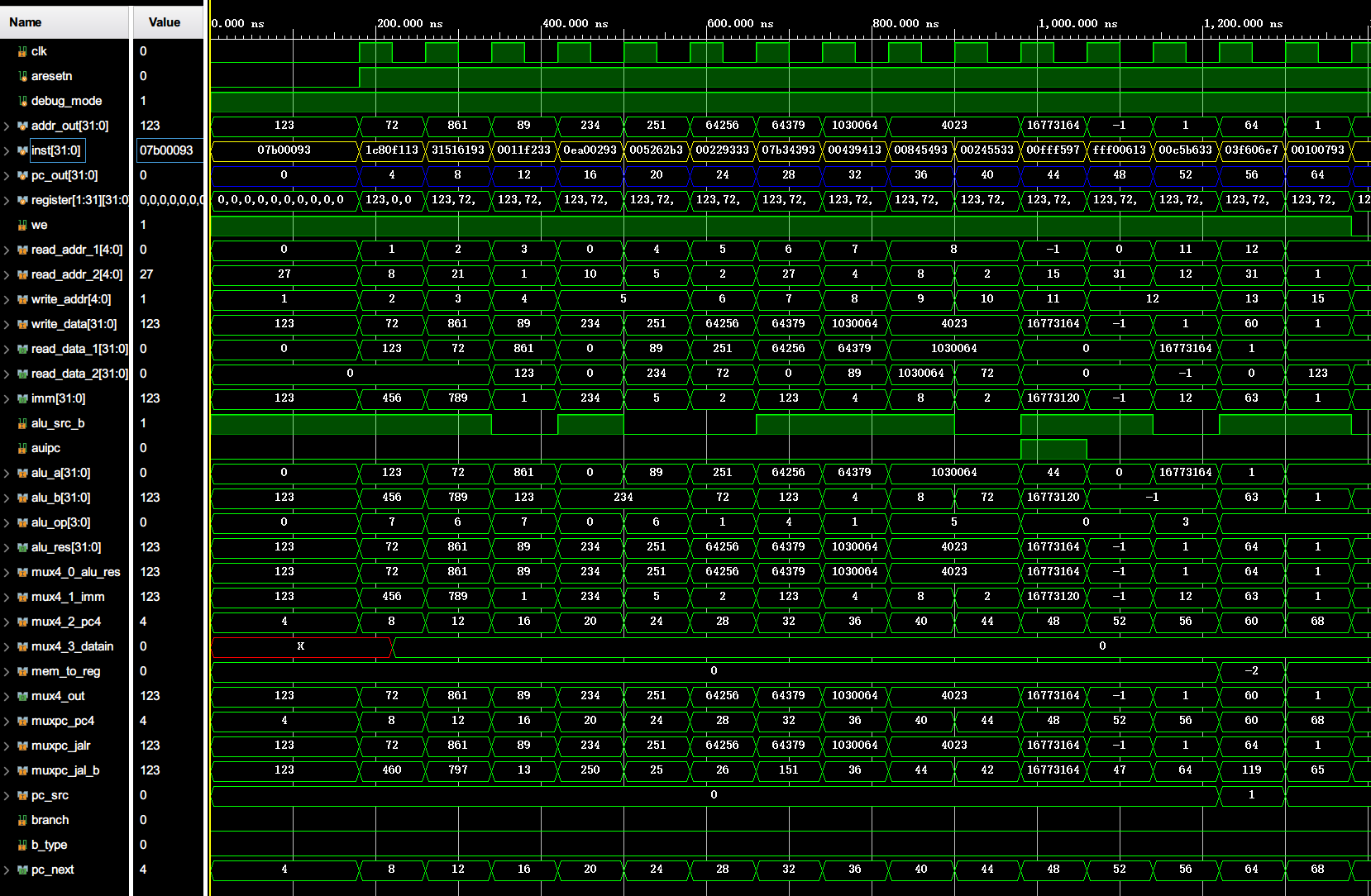
Bonus 范围的指令在前面设计控制单元的时候就已经考虑了,所以只需要测试这些指令即可。简单写了一个包含这些指令的 RISC-V 汇编文件:
.section .text
.globl _start
_start:
    addi    x1,     x0,     123     # x1 = 123
    andi    x2,     x1,     456     # x2 = 72
    ori     x3,     x2,     789     # x3 = 861
    and     x4,     x3,     x1      # x4 = 89
    addi    x5,     x0,     234     # x5 = 234
    or      x5,     x4,     x5      # x5 = 251 (0xfb)
    sll     x6,     x5,     x2      # x6 = 64256 (0xFB00)
    xori    x7,     x6,     123     # x7 = 64379 (0xFB7B)
    slli    x8,     x7,     4       # x8 = 1030064 (0xFB7B0)
    srli    x9,     x8,     8       # x9 = 4023 (0xFB7)
    srl     x10,    x8,     x2      # x10 = 4023 (0xFB7)
    auipc   x11,    0xFFF           # x11 = 0xFFF02C
    addi    x12,    x0,     -1      # x12 = -1
    sltu    x12,    x11,    x12     # x12 = 1
    jalr    x13,    63(x12)         # x13 = 60
    addi    x14,    x0,     1       # won't exec
Label:
    addi    x15,    x0,     1
00010074 <_start>:
   10074:   07b00093    li  ra,123
   10078:   1c80f113    andi    sp,ra,456
   1007c:   31516193    ori gp,sp,789
   10080:   0011f233    and tp,gp,ra
   10084:   0ea00293    li  t0,234
   10088:   005262b3    or  t0,tp,t0
   1008c:   00229333    sll t1,t0,sp
   10090:   07b34393    xori    t2,t1,123
   10094:   00439413    slli    s0,t2,0x4
   10098:   00845493    srli    s1,s0,0x8
   1009c:   00245533    srl a0,s0,sp
   100a0:   00fff597    auipc   a1,0xfff
   100a4:   fff00613    li  a2,-1
   100a8:   00c5b633    sltu    a2,a1,a2
   100ac:   03f606e7    jalr    a3,63(a2)
   100b0:   00100713    li  a4,1

000100b4 <Label>:
   100b4:   00100793    li  a5,1
memory_initialization_radix = 16;
memory_initialization_vector =
07b00093, 1c80f113, 31516193, 0011f233, 0ea00293, 005262b3, 00229333, 07b34393, 00439413, 00845493, 00245533, 00fff597, fff00613, 00c5b633, 03f606e7, 00100713, 00100793;


通过分析 pc、中间值等以及和汇编代码实际效果(注释里写了)对比,可以发现这些 bonus 指令都正常执行了。上板测试也没有问题。

